|
PIPER
1.0.1
|
|
PIPER
1.0.1
|
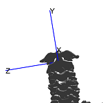
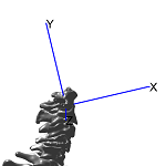
The direct kinematics model (DK) provides the relative location of segments and their landmarks for specific joint angles defined by the user.
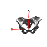
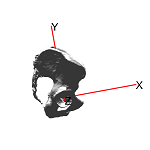
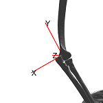
The DK model was developed consisting of a specific set of articulated segments. The DK model is described by an articulation chain of segments and the individual joints between them. For each joint a coordinate system (JCS) is defined that connects two adjacent segments and describes the joint rotation axes and their rotation sequence. Each segment is a rigid body that represents one or more bones (see following table). The DK model is positioned by changing the angles of these joints. Local coordinate systems (LCS) of the segments, were essentially constructed using anatomical landmarks, following the ISB recommendations [Wu 2002; Wu 2005], and they are used to define the relative angles of the joints. The following tables summarize the segments and the joints defined into the DK model and the anatomical landmarks employed for the definition of the local coordinate systems.
| Segment | Alias | Body parts |
|---|---|---|
| Pelvis | Pelvis | Pelvic_skeleton, Sacrum, Left_hip_bone, Right_hip_bone |
| Thigh* | Femur_L | Left_femur |
| Lower leg* | Tibia_L | Left_tibia, Left_fibula |
| Foot* | Foot_L | Left_foot |
| Patella* | Patella_L | Left_patella |
| Lumbar vertebrae (L5-L1)** | Lumbar_L5,..., Lumbar_L1 | Fifth_lumbar,...,First_lumbar |
| Thoracic vertebrae (T12-T01)** | Thoracic_T12,..., Thoracic_T01 | Twelfth_thoracic,..., First_thoracic |
| Cervical vertebrae (C7-C1)** | Cervical_C7,..., Cervical_C1 | Seventh_cervical,..., First_cervical |
| Skull | Skull | Skull |
| Mandible | Mandible | Mandible |
| Clavicle* | Clavicle_L | Left_clavicle |
| Scapula* | Scapula_L | Scapula_L |
| Arm* | Humerus_L | Left_humerus |
| Forearm* | Ulna_L | Left_ulna, Left_radius |
| Sternum | Sternum | Sternum |
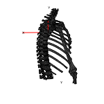
| Rib cage | RibCage | Left_first_rib-Right_twelfth_rib |
| Joint | Segment 1 | Segment 2 |
|---|---|---|
| Reference | Pelvis | Environment |
| L5-Sacrum | Pelvis | Fifth lumbar vertebra |
| L4-L5 vertebral arch | Fifth lumbar vertebra | Fourth lumbar vertebra |
| L3-L4 vertebral arch | Fourth lumbar vertebra | Third lumbar vertebra |
| L2-L3 vertebral arch | Third lumbar vertebra | Second lumbar vertebra |
| L1-L2 vertebral arch | Second lumbar vertebra | First lumbar vertebra |
| T12-L1 vertebral arch | First lumbar vertebra | Twelfth thoracic vertebra |
| T11-T12 vertebral arch | Twelfth thoracic vertebra | Eleventh thoracic vertebra |
| T10-T11 vertebral arch | Eleventh thoracic vertebra | Tenth thoracic vertebra |
| T9-T10 vertebral arch | Tenth thoracic vertebra | Ninth thoracic vertebra |
| T8-T9 vertebral arch | Ninth thoracic vertebra | Eighth thoracic vertebra |
| T7-T8 vertebral arch | Eighth thoracic vertebra | Seventh thoracic vertebra |
| T6-T7 vertebral arch | Seventh thoracic vertebra | Sixth thoracic vertebra |
| T5-T6 vertebral arch | Sixth thoracic vertebra | Fifth thoracic vertebra |
| T4-T5 vertebral arch | Fifth thoracic vertebra | Fourth thoracic vertebra |
| T3-T4 vertebral arch | Fourth thoracic vertebra | Third thoracic vertebra |
| T2-T3 vertebral arch | Third thoracic vertebra | Second thoracic vertebra |
| T1-T2 vertebral arch | Second thoracic vertebra | First thoracic vertebra |
| C7-T1 vertebral arch | First thoracic vertebra | Seventh cervical vertebra |
| C6-C7 vertebral arch | Seventh cervical vertebra | Sixth cervical vertebra |
| C5-C6 vertebral arch | Sixth cervical vertebra | Fifth cervical vertebra |
| C4-C5 vertebral arch | Fifth cervical vertebra | Fourth cervical vertebra |
| C3-C4 vertebral arch | Fourth cervical vertebra | Third cervical vertebra |
| C2-C3 vertebral arch | Third cervical vertebra | Second cervical vertebra (Axis) |
| C1-C2 vertebral arch | Second cervical vertebra (Axis) | First cervical vertebra (Atlas) |
| C1-Skull | First cervical vertebra (Atlas) | Skull |
| Skull-Mandible | Skull | Mandible |
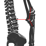
| Left hip | Pelvis | Left femur |
| Left tibiofemoral | Left femur | Left lower leg |
| Left ankle | Left lower leg | Left foot |
| Left patellofemoral | Left femur | Left patella |
| Left sternoclavicular | T1 | Left clavicle |
| Scapula-Clavicle | Left clavicle | Left scapula |
| Left glenohumeral | Left clavicle | Left arm |
| Left elbow | Left arm | Left forearm |
| Left clavicle-sternum | Left cleavicle | Sternum |
| T4-rib cage | T4 | Rib cage |
| Segment | LM 1 | LM 2 | LM 3 | LM 4 |
|---|---|---|---|---|
| Pelvis | Right_acetabular_center | Left_acetabular_center | Center_lower_plate_of_L5 | |
| Lumbar L5 | Anterior_midpoint_of_the_body_of_L5 | Posterior_midpoint_of_the_body_of_L5 | Center_lower_plate_of_L5 | Center_upper_plate_of_L5 |
| Lumbar L4 | Anterior_midpoint_of_the_body_of_L4 | Posterior_midpoint_of_the_body_of_L4 | Center_lower_plate_of_L4 | Center_upper_plate_of_L4 |
| Lumbar L3 | Anterior_midpoint_of_the_body_of_L3 | Posterior_midpoint_of_the_body_of_L3 | Center_lower_plate_of_L3 | Center_upper_plate_of_L3 |
| Lumbar L2 | Anterior_midpoint_of_the_body_of_L2 | Posterior_midpoint_of_the_body_of_L2 | Center_lower_plate_of_L2 | Center_upper_plate_of_L2 |
| Lumbar L1 | Anterior_midpoint_of_the_body_of_L1 | Posterior_midpoint_of_the_body_of_L1 | Center_lower_plate_of_L1 | Center_upper_plate_of_L1 |
| Thoracic T12 | Anterior_midpoint_of_the_body_of_T12 | Posterior_midpoint_of_the_body_of_T12 | Center_lower_plate_of_T12 | Center_upper_plate_of_T12 |
| Thoracic T11 | Anterior_midpoint_of_the_body_of_T11 | Posterior_midpoint_of_the_body_of_T11 | Center_lower_plate_of_T11 | Center_upper_plate_of_T11 |
| Thoracic T10 | Anterior_midpoint_of_the_body_of_T10 | Posterior_midpoint_of_the_body_of_T10 | Center_lower_plate_of_T10 | Center_upper_plate_of_T10 |
| Thoracic T09 | Anterior_midpoint_of_the_body_of_T9 | Posterior_midpoint_of_the_body_of_T9 | Center_lower_plate_of_T9 | Center_upper_plate_of_T9 |
| Thoracic T08 | Anterior_midpoint_of_the_body_of_T8 | Posterior_midpoint_of_the_body_of_T8 | Center_lower_plate_of_T8 | Center_upper_plate_of_T8 |
| Thoracic T07 | Anterior_midpoint_of_the_body_of_T7 | Posterior_midpoint_of_the_body_of_T7 | Center_lower_plate_of_T7 | Center_upper_plate_of_T7 |
| Thoracic T06 | Anterior_midpoint_of_the_body_of_T6 | Posterior_midpoint_of_the_body_of_T6 | Center_lower_plate_of_T6 | Center_upper_plate_of_T6 |
| Thoracic T05 | Anterior_midpoint_of_the_body_of_T5 | Posterior_midpoint_of_the_body_of_T5 | Center_lower_plate_of_T5 | Center_upper_plate_of_T5 |
| Thoracic T04 | Anterior_midpoint_of_the_body_of_T4 | Posterior_midpoint_of_the_body_of_T4 | Center_lower_plate_of_T4 | Center_upper_plate_of_T4 |
| Thoracic T03 | Anterior_midpoint_of_the_body_of_T3 | Posterior_midpoint_of_the_body_of_T3 | Center_lower_plate_of_T3 | Center_upper_plate_of_T3 |
| Thoracic T02 | Anterior_midpoint_of_the_body_of_T2 | Posterior_midpoint_of_the_body_of_T2 | Center_lower_plate_of_T2 | Center_upper_plate_of_T2 |
| Thoracic T01 | Anterior_midpoint_of_the_body_of_T1 | Posterior_midpoint_of_the_body_of_T1 | Center_lower_plate_of_T1 | Center_upper_plate_of_T1 |
| Cervical C7 | Anterior_midpoint_of_the_body_of_C7 | Posterior_midpoint_of_the_body_of_C7 | Center_lower_plate_of_C7 | Center_upper_plate_of_C7 |
| Cervical C6 | Anterior_midpoint_of_the_body_of_C6 | Posterior_midpoint_of_the_body_of_C6 | Center_lower_plate_of_C6 | Center_upper_plate_of_C6 |
| Cervical C5 | Anterior_midpoint_of_the_body_of_C5 | Posterior_midpoint_of_the_body_of_C5 | Center_lower_plate_of_C5 | Center_upper_plate_of_C5 |
| Cervical C4 | Anterior_midpoint_of_the_body_of_C4 | Posterior_midpoint_of_the_body_of_C4 | Center_lower_plate_of_C4 | Center_upper_plate_of_C4 |
| Cervical C3 | Anterior_midpoint_of_the_body_of_C3 | Posterior_midpoint_of_the_body_of_C3 | Center_lower_plate_of_C3 | Center_upper_plate_of_C3 |
| Cervical C2 | Anterior_midpoint_of_the_body_of_C2 | Posterior_midpoint_of_the_body_of_C2 | Center_lower_plate_of_C2 | Center_upper_plate_of_C2 |
| Cervical C1 | VC1 | DC1 | Center_lower_plate_of_C1 | Center_atlanto_occipital_joint |
| Scull | Center_atlanto_occipital_joint | Left_porion | Right_porion | Nasion |
| Mandible | Left_jaw_angle | Right_jaw_angle | Inferior_crest_of_the_jaw | |
| Thigh L | Medial_epicondyle_of_left_femur | Lateral_epicondyle_of_left_femur | Left_acetabular_center | |
| Lower leg L | Lateral_point_lateral_condyle_of_left_tibia | Medial_point_medial_condyle_of_left_tibia | Tip_lateral_malleolus_of_left_fibula | Tip_medial_malleolus_of_left_tibia |
| Foot L | Lateral_point_lateral_condyle_of_left_tibia | Medial_point_medial_condyle_of_left_tibia | Tip_lateral_malleolus_of_left_fibula | Tip_medial_malleolus_of_left_tibia |
| Patella L | PatellaL_anterior_center | PatellaL_lateral | PatellaL_medial | PatellaL_distal |
| Clavicle L | Dorsal_point_of_left_acromioclavicular_joint | Ventral_point_of_left_sternoclavicular_joint | Anterior_midpoint_of_the_body_of_T8 | Anterior_midpoint_of_the_body_of_C7 |
| Scapula L | Dorsal_point_of_left_acromioclavicular_joint | Angulus_acromialis_of_left_scapula | Angulus_inferior_of_left_scapula | Trigonum_spinae_of_left_scapula |
| Arm L | Lateral_epicondyle_of_left_humerus | Medial_epicondyle_of_left_humerus | Head_center_of_left_humerus | |
| Forearm L | Lateral_epicondyle_of_left_humerus | Medial_epicondyle_of_left_humerus | Styloid_process_of_left_radius | Styloid_process_of_left_ulna |
| Sternum | Left_sternum_sternoclavicular_joint | Right_sternum_sternoclavicular_joint | Substernale_(xyphoid_process) | Jugular_notch |
| Rib cage | Ventral_point_of_left_sternoclavicular_joint | Right_sternum_sternoclavicular_joint | Anterior_midpoint_of_the_body_of_T4 | Anterior_midpoint_of_the_body_of_T10 |
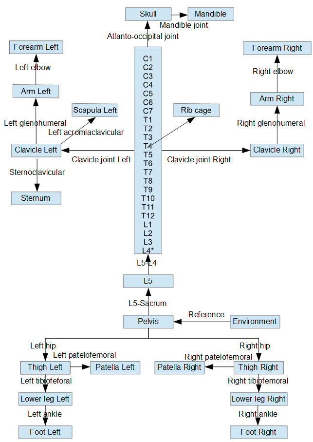
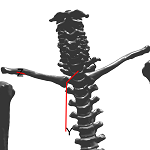
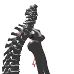
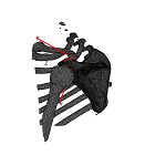
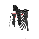
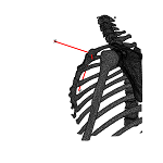
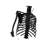
The segments are articulated to each other following a tree structure, with the pelvis being the root of this structure (see following figure). Three rotational degrees of freedom (DOF) are allowed for each joint, with the exception of the joint connecting the pelvis with the environment that three additional translational DOF are allowed. The orientation of each segment is computed relative to its predecessor in the tree structure, taking into account the rotational angles of the joint connecting the segments.
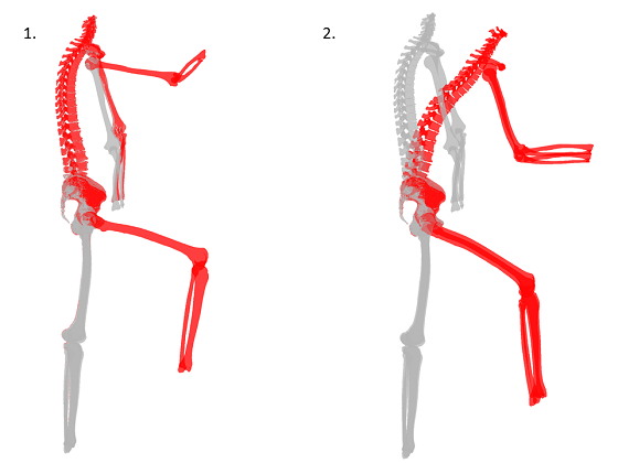
The following figure demonstares two examples of positioning the reference model, by using joint angles defined by the user. Initially, the DK model is constructed by calling the function "CreatePiperModel.m". The model structure in .txt format and anatomical landmarks coordinates in .csv format serve as inputs for this function. This function computes LCS using the anatomical landmarks coordinates, articulates the segments using the model structure and computes the local coordinate systems (figure bellow, gray skeleton). The function provides the dimensions of the articulated model and the anatomical landmarks coordinates both in global coordinate system and in LCS. The function "RepositionSkeletonByDK.m" is used to re-position the skeleton. The dimensions and the structure of the articulated model and the joint angles corresponding the desired posture serve as input for this function. The function computes the new position of each segment using the position of its predecessor in the tree structure and the angles of the joint connecting the segments as defined by the user. The function provides the anatomical landmarks coordinates in the new posture, expressed in both the global coordinate system and in LCS (figure bellow, red skeleton). For the first example the flexion angles of the right hip, right knee, right glenohumeral and right elbow were increased 60, -80, 80 and -60° respectively. These flexion angles resulted in the posture represented with the red skeleton (figure bellow left, red skeleton). Although only flexion angles were defined, it can be noticed that the forearm is also internally rotated relative to the spine. This occurred because the computation of the position of the forearm segment is based on the position and orientation of the arm and the angles defined for the elbow joint. As the arm is inverted the elbow flexion causes the forearm to move internally relatively to the spine. For the second example, the joint angles of the driving posture were employed (figure bellow right).
| Step | Action | Script |
|---|---|---|
| 1 | Symmetrize skeleton | SymLMs |
| 2 | Compute joint angles of the driving posture (target posture) | CreatePersonalizedPiperModel |
| 3 | Compute joint coordinate systems and express anatomical landmarks with repect to LCS for source skeletons | CreatePersonalizedPiperModel |
| 4 | Compute the coordinates of the anatomical landmarks on the target posture | RepositionSkeletonByDK |
| Script | Input | Output | Description |
|---|---|---|---|
| CreatePersonalizedPiperModel(sbj) | Piper.Model.txt (sbj)_LMsImport.csv ZeroJointAngles.txt | (sbj).ScannedPosture.LMs.csv (sbj).ScannedPosture.JointAngles.csv (sbj).JointCenters.csv (sbj).Dimensions.mat (sbj).Body.mat | Computes local coordinate systems for each segment and computes the positions of the anatomical landmarks with respect to the GCS and LCS |
| RepositionSkeletonByDK(sbj) | Piper.Model.txt (sbj).Dimensions.mat (sbj).Body.mat DrivingPosture.JointAngles.csv | (sbj).DrivingPosture.LMs.csv | Positions the articulated model based on joint angles defined by the user and computes the positions of the anatomical landmarks in the target posture with respect to the GCS and LCS |
| SymLMs | (sbj)_lm.csv | (sbj)_LMsSym.csv | i) Creates symmetrized to the left extremities anatomical landmarks on the respective right extrimities ii) Modifies the input landmarks set such as the headers are capitalized and landmarks are registered to segments instead of body parts (Alias table 1) ex. Styloid_process_of_left_radius Left_radius Ulna_L Left_ischial_tuberosity Left_hip_bone Pelvis |
| Segment_(segment name) | Previous segment in the kinematic chain, anatomical landmarks | LCS A structure variable including the the segment, body parts, LCS, axes rotation sequence, distal and proximal joints | Defines |
| Script | Description |
|---|---|
| BatchProcess4ComputingLMsInScannedAndDrivingPostures | Executes the CreatePersonalizedPiperModel and RepositionSkeletonByDK scripts for all the selected sbj |
| BatchProcess4SymLMs | Executes the SymLMs script for all the selected sbj |
| File | Description |
|---|---|
| Piper.Model.txt | Defines the structure of the model: Joints, segments and containing body parts, anatomical landmarks to be used for LCS |
| (sbj)_lm.csv | Anatomical landmarks coordinates (name, body part, x, y, z) |
| (sbj)_LMsSym.csv | Anatomical landmarks coordinates (name, segment, x, y, z) |
| ZeroJointAngles.txt | Zero values for all the joint angles |
| (sbj).ScannedPosture.LMs.csv | Anatomical landmarks coordinates for the scan posture (name, segment, x, y, z, X, Y, Z) |
| (sbj).DrivingPosture.LMs.csv | Anatomical landmarks coordinates for the driving posture (name, segment, x, y, z, X, Y, Z) |
| (sbj).ScannedPosture.JointAngles.csv | Joint angles for the articulated model |
| (sbj).JointCenters.csv | Coordinates of the joint centers |
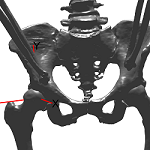
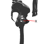
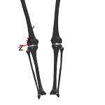
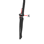
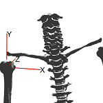
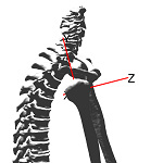
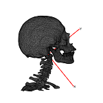
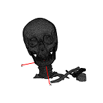
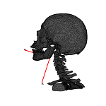
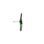
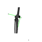
| Joint | Definition | Anterior view | Lateral view | ||||
|---|---|---|---|---|---|---|---|
| Pelvis-Environment |
| 
| 
| ||||
| Hip |
| 
| 
| ||||
| Knee |
| 
| 
| ||||
| C2-C3 |
| 
| 
| ||||
| Sternoclavicular |
| 
| 
| ||||
| Glenohumeral |
| 
| 
| ||||
| Skull |
| 
| 
| ||||
| Mandible |
| 
| 
| ||||
| Patella |
| 
| 
| ||||
| Scapula |
| 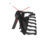
| 
| ||||
| Sternum |
| 
| 
| ||||
| RibCage |
| 
| 
| ||||
| Elbow |
| 
| 
|
Wu G et al., 2002. ISB recommendation on definitions of joint coordinate system of various joints for the reporting of human joint motion - Part I: ankle, hip, and spine. Journal of Biomechanics 35: 543 - 548.
Wu G et al., 2005. ISB recommendation on definitions of joint coordinate systems of various joints for the reporting of human joint motion - Part II: shoulder, elbow, wrist and hand. Journal of Biomechanics 38: 981 - 992.
 1.8.10
