This module implements a Contour based approach to position the Human Body Model.
The GBP method of mesh modification is based on the use of contours that envelop the body. The module has primarily two aspects: (1) positioning and (2) personalization.
The method of mesh modification is based on the use of contours that envelop the body. The contour based deformation (personalization as well as repositioning) method has 4 steps
- Contour Generation
- Delaunay Mapping
- Contour Transformation
- Remapping.
In the first step, we load the contourCL.xml file from the positioning window. The cotnour Control Line(contourCL) is a yellow line structure made up by joining the anatomical landmarks on the Human Body Model. With the help of this contourCL contours are generated all around the GHBMC model. These contours and some typical key points (for instance the nodes of the bones in some cases) are used to generate Delaunay Tetrahedrons which cover whole model.
All the mesh nodes of the model are then mapped to these Delaunay Tetrahedrons using volume coordinates. Third step consist of transformation of these contours as per the desired input (for instance personalization / repositioning parameters). It is expected that the key points (for instance the bone nodes) are also transformed using the same parameters. Figure 1 shows a set of contours for the GHBMC model.
At the end of third step final positions for all contour points as well as all the key points will be available in the final position. Using these transformed contours and key points, the mapped mesh nodes are remapped and their new positions are determined. This completes the deformation process.
Target Input : For target based personalization and positioning Contour Deformation module handles the following targets:
- For positioning it handles the Landmark Targets
- For personalization it can handle GEBOD target and ANSUR targets generated in the Anthropometric Module.
Metadata
The required metadata for positioning and personalization are :
- Required : contourCL, Landmarks needed to define contourCL, Skin Entity, Flesh GenericMetadata, Contours
- contourCL : contour control line is formed from the DMA landmarks. It contains the body region and joint information.
- Contours : Contours are typically closed curves like circle, ellipse, polyline or cubic splines. The contour modification routines shall modify them accordingly.
- Landmarks (defined to create contourCL)
- The bones entities (as defined in Appendix: List of entities)
- Genericmetadata
UI for Contour Deformation Module
POSITIONING
Allows the user to carry out the Positioning process. The UI of the POSITIONING Window consists of the following features :
- Load ContourCL file : It loads the contourCL metadata. It is required for generation of contours around the body and the information required to reposition the model at a specified joint by giving a specific angle wih respect to the current position of the model. In current piper application contourCL is the yellow highlighted line segment. It is basically made up by joining the anatomical landmarks of the human body.
- Load Contours (for hip positioning) File icon : User can externally load the contours. Curently It is used when one wants to the the repositioning at hip joint. User needs to load the contours from following path : {model_path}/GHBM/metadata/contours_for_hip/Contour_Input.txt . Deform Contours button will remain disabled for Hip Joint unless user loads the required contours from the specified path.
- Module Opacity : It controls the opacity of human body model.
- Contour CL opacity : It controls the opacity of contourCL and generated contours.
- Repositioning Parameters : This section takes input from the user about the joint at which he wants to do the positioning, the type of movement, the side(left/right) and the angle(with respect to the current position).
- Select joint : Select the joint from a list of joints- Knee, Ankle, Hip, Neck, Elbow or Wrist
- Select side : Left or Right Side
- Select type : Type of movement- Flexion/Extension, Inversion/Aversion, Lateral Rotation or Lateral Flexion etc.
- Angle : Angle must be given with respect to the current position. eg. A value of 10 degree at LEFT KNEE joint shall do a flexion of knee by an angle of 10 degree.
- Generate Contours : Contours are typically closed non-intersecting curves like circle, ellipse or a polyline enveloping the HBM. In some cases they can also be open cubic splines. The contour modification routines shall modify them accordingly. Typically, the contours should not be on the skin but slightly bigger and away from surface of mesh. Generate contour will create these contours.
- Deform Contours : Contours will be deformed by the input angle at the selected joint.
- Reposition : The model will be repositioned.
- Use Landmark Switch : If the positioning is to be done using the landmark targets import the target file from the file menu and click on this switch to start the positioning through landmark targets
- Process Landmark Targets : Click on this button to compute the input required to do the positioning.
- Continue : Click on this button to continue with the process of landmark target positioning till a prompt of positioning complete comes up
PERSONALIZATION
Allows the user to personalize the model using a number of parameters.
The Personalization window UI :
- Load Personalization Contours : User needs to load the contours for personalization. The path for the Personalization_Contours is "{model}\GHBM\metadata\contour_input_for_personalization"
- Load Body Data : Load BodyData.txt file from the path : "{model}\GHBM\metadata\BodyData" to enable the personalization process
- Load Anthropometric Target File : Load the target file generated from the anthropometric module, it contain the values corresponding to ANSUR body dimensions. Load this file when you need to do the personalization using the target ANSUR body dimensions.
- Options : At present the user can populate the 35 GEBOD dimension values by selecting among 5th,50th,75th or 95th percentile or by selecting the generated GEBOD or ANSUR target dimensions. GEBOD & ANSUR target dimensions can be generated through Anthorpometric Module.
- Personalize : Personalize button will start the personalization for the full GHBMC model for the given 35 parameter values
GEBOD Body Dimension Descriptions:
- 1. WEIGHT: Subject stands on scales (nude or wearing lightweight undergarments) with feet parallel and weight distributed equally on both feet.
- 2. STANDING HEIGHT: Subject stands erect, head in the Frankfort plane, heels together, and weight distributed equally on both feet. With the arm of the anthropometer firmly 64 MADYMO Utilities Manual Release 7.5 touching the scalp, measure the vertical distance from the standing surface to the top of the head.
- 3. SHOULDER HEIGHT: Subject stands erect looking straight ahead, heels together, and weight distributed equally on both feet. With an anthropometer, measure the vertical distance from the standing surface to the right acromial landmark.
- 4. ARMPIT HEIGHT: Measurement derived by subtracting Scye Circumference divided by
 . from Shoulder Height (see above). Scye Circumference: Subject stands erect looking straight ahead. The right arm is abducted sufficiently to allow placement of a tape into the axilla. With a tape passing through the axilla, over the anterior and posterior vertical scye landmarks and over the right acromial landmark, measure the circumference of the scye. The axillary tissue is not compressed.
- 5. WAIST HEIGHT: Subject stands erect, his head in the Frankfort plane.Using an anthropometer, measure the distance from the standing surface to the omphalion landmark. The subject must not pull in his stomach.
- 6. SEATED HEIGHT: Subject sits erect, head in the Frankfort plane, upper arms hanging relaxed, forearms and hands extended forward horizontally. With the anthropometer arm firmly touching the scalp, measure the vertical distance from the sitting surface to the top of the head.
- 7. HEAD LENGTH: Subject sits. With a spreading calliper, measure in the midsagittal plane the maximum length of the head between the glabella landmark and the occiput.
- 8. HEAD BREADTH: Subject sits. With a spreading calliper measure the maximum horizontal breadth of the head above the level of the ears.
- 9. HEAD TO CHIN HEIGHT: Subject stands under the headboard looking straight ahead. The headboard is adjusted so that its vertical and horizontal planes are in firm contact with the back and the top of the head. Positioning the head in the Frankfort plane and using the special gauge, measure the vertical distance from the horizontal plane to the menton landmark.
- 10. NECK CIRCUMFERENCE: Subject sits erect, head in the Frankfort plane. A piece of dental tape is placed around the neck, passing over all four neck landmarks. The measurer marks off with her thumbnail a length of tape corresponding to the subject’s neck circumference, and then measures this tape segment with a standard tape.
- 11. SHOULDER BREADTH: Subject sits erect looking straight ahead, upper arms hanging relaxed, forearms and hands extended forward horizontally. With a beam calliper, measure the distance between the acromial landmarks.
- 12. CHEST DEPTH: Subject stands erect looking straight ahead, heels together, and weight distributed equally on both feet. With a beam calliper, measure the horizontal depth of the trunk at the level of the bustpoint landmarks. The reading is made at the point of maximum quiet inspiration. 65 Release 7.5 MADYMO Utilities Manual
- 13. CHEST BREADTH: Subject stands erect looking straight ahead with arms slightly abducted. With a beam calliper, measure the horizontal distance across the trunk at the level of the bustpoint landmarks.
- 14. WAIST DEPTH: Subject stands erect looking straight ahead, arms at sides heels together, and weight distributed equally on both feet. With a beam calliper, measure the horizontal depth of the trunk at the level of the waist landmarks. The reading is made at the point of maximum quiet inspiration. The subject must not pull in her stomach.
- 15. WAIST BREADTH: Subject stands erect looking straight ahead with arms slightly abducted. With a beam calliper, measure the horizontal breadth across the trunk at the level of the waist landmarks.
- 16. BUTTOCK DEPTH: Subject stands erect, heels together and weight distributed equally on both feet. With a beam calliper, measure the horizontal depth of the trunk at the level of the buttock landmark.
- 17. HIP BREADTH, STANDING: Subject stands erect, heels together and weight distributed equally on both feet. With a beam calliper, measure the maximum horizontal breadth of the hips.
- 18. SHOULDER TO ELBOW LENGTH: Subject stands erect looking straight ahead and with arms relaxed. With a beam calliper held parallel to the long axis of the right upper arm, measure the distance from the acromial landmark to the radiale landmark.
- 19. FOREARM-HAND LENGTH: Measurement derived by summing Radiale- Stylion Length and Hand Length. Radiale-Stylion Length: Subject stands erect with arms relaxed. With a beam calliper held parallel to the long axis of the right forearm, measure the distance from the radiale landmark to the stylion landmark. Hand Length: Subject sits, right forearm and hand raised with palm up. The fingers are together and straight but not hyper-extended. With the bar of a sliding calliper parallel to the long axis of the hand, measure the distance from the wrist landmark to the dactylion.
- 20. BICEPS CIRCUMFERENCE: Subject stands with right arm slightly abducted. With a tape held in a plane perpendicular to the long axis of the upper arm, measure the circumference of the arm at the level of the biceps landmark.
- 21. ELBOW CIRCUMFERENCE: Subject stands, right upper arm raised so that its long axis is horizontal, elbow flexed 90 degrees, fist tightly clenched and biceps strongly contracted. With a tape passing over the tip and through the crotch of the elbow, measure the circumference of the elbow.
- 22. FOREARM CIRCUMFERENCE: Subject stands erect with right arm slightly abducted and hand relaxed. With a tape held in a plane perpendicular to the long axis of the forearm, measure the circumference of the arm at the level of the forearm landmark.
- 23. WRIST CIRCUMFERENCE: Subject stands with right arm slightly abducted. With a tape held in a plane perpendicular to the long axis of the forearm and hand, measure the circumference of the wrist at the level of the stylion landmark. 66 MADYMO Utilities Manual Release 7.5
- 24. KNEE HEIGHT, SEATED: Subject sits with his feet resting on a surface adjusted so that the knees are bent at about right angles. Using an anthropometer, measure the vertical distance from the footrest surface to the suprapatella landmark on the right knee.
- 25. THIGH CIRCUMFERENCE: Subject stands erect, heels approximately 10 cm apart, and weight distributed equally on both feet. With a tape held in a plane perpendicular to the long axis of the right thigh measure the circumference of the thigh at the level of the lowest point on the gluteal furrow. Where the furrow is deeply indented, the measurement is made just distal to the furrow.
- 26. UPPER LEG CIRCUMFERENCE: Measurement derived by summing the Thigh Circumference (see above) and the Knee Circumference (see below) and dividing the sum by two to obtain the average.
- 27. KNEE CIRCUMFERENCE: Subject stands erect, heels approximately 10 cm apart, and weight distributed equally on both feet. With a tape held in a plane perpendicular to the long axis of the right leg, measure the circumference of the knee at the level of the mid patella landmark. The subject must not tense her knee during the measurement.
- 28. CALF CIRCUMFERENCE: Subject stands erect, heels approximately 10 cm apart, and weight distributed equally on both feet. With a tape held in a plane perpendicular to the long axis of the right lower leg, measure the circumference of the calf at the level of the calf landmark.
- 29. ANKLE CIRCUMFERENCE: Subject stands erect with weight distributed equally on both feet. With a tape held in a plane perpendicular to the long axis of the right lower leg, measure the circumference of the leg at the level of the ankle landmark.
- 30. ANKLE HEIGHT, OUTSIDE: Subject stands with weight distributed equally on both feet. With the special measuring block, measure the vertical distance from the standing surface to the lateral malleolus landmark on the right leg.
- 31. FOOT BREADTH: Subject stands erect, right foot in the measuring box, left foot on a board of equal height, and weight distributed equally. The right foot is positioned so that its long axis is parallel to the side of the box, the heel touches the rear of the box, and the medial metatarsal-phalangeal joint touches the widest part of the foot, measure on the scale of the box the breadth of the foot.
- 32. FOOT LENGTH: Subject stands erect, right foot in the measuring box, left foot on a board of equal height, and weight distributed equally. The right foot is positioned so that its long axis is parallel to the side of the box, the heel touches the rear of the box, and the medial metatarsal-phalangeal joint touches the side of the box. With the measuring block touching the tip of the most protruding toe, measure on the scale of the box the length of the foot.
- 33. HAND BREADTH: Subject sits with right hand resting on a table, palm up, fingers extended and together. The thumb is held away from the hand. Using the sliding caliper, measure the maximum breadth from Metacarpale II to Metacarpale V. 67 Release 7.5 MADYMO Utilities Manual
- 34. HAND LENGTH: Subject sits with his right hand resting flat on a table, palm up, fingers extended and together. With the bar of the sliding caliper parallel to the long axis of the hand, measure the distance from the wrist landmark to the tip of the finger.
- 35. HAND DEPTH: Subject.s right hand is held palm down with fingers extended and together, narrow profile towards the measurerer. Maintaining light pressure on the spreading caliper, measure the thickness of the hand at the metacarpalphalangeal joint of the third finger.
Display Tab
Allows the user to selectively display of entities, landmarks, generic metadatas, frames, joints, contours and targets.
Limitations
The current repositioning works for full GHBMC Model. So to proceed with the repositioniong one has to import the FULL GHBMC.
- For repositioniong at pelvis joint one has to first load the Contour_Input.txt file from the "{model_path}/GHBM/metadata/contours_for_hip/" folder. After loading the Contour_Input.txt file the contours will be generated for the model.
- Hip repositioning will then require the basic inputs like type of movement(flexion/extension,internal/external rotation or abduction/aduction), angle and left/right side.
POSITIONING Procedure
Steps to re-position the model using the contour deformation module :
- 1. Open Repositioning window by clicking on the "Positioning" button on the right panel
- 2. Load the contourCL from contourDeformation Module
- 3. Select the joint to be re-positioned and & type of movement intended :
- 3a) Knee : type of repositioning [flexion/extension]
- 3b) Ankle : type of repositioning [flexion/extension, inversion/aversion]
- 3c) Neck : type of repositioning [flexion/extension, lateral rotation, lateral flexion/extension]
- 3d) Elbow : type of repositioning [flexion/extension, pronation/supination]
- 3e) Wrist : type of repositioning [flexion/extension]
- 3f) Hip : type of repositioning [flexion/extension, abduction/adduction, internal/external rotation]
- 3fa) Click on the button with the "File icon" and load the contour file present in piper_model/GHBM/metadata/contours_for_hip folder
- 4. Enter the angle by which you want to do the selected movement at the selected joint
- 5. Click on the "Generate contours" button to create the contours and wait for the contours to be generated
- 6. Click on the "Deform Contours" button to deform the contours.
- 7. Click on the "Reposition" button to re-position the model to the new position and wait for the re-positioning to be completed.
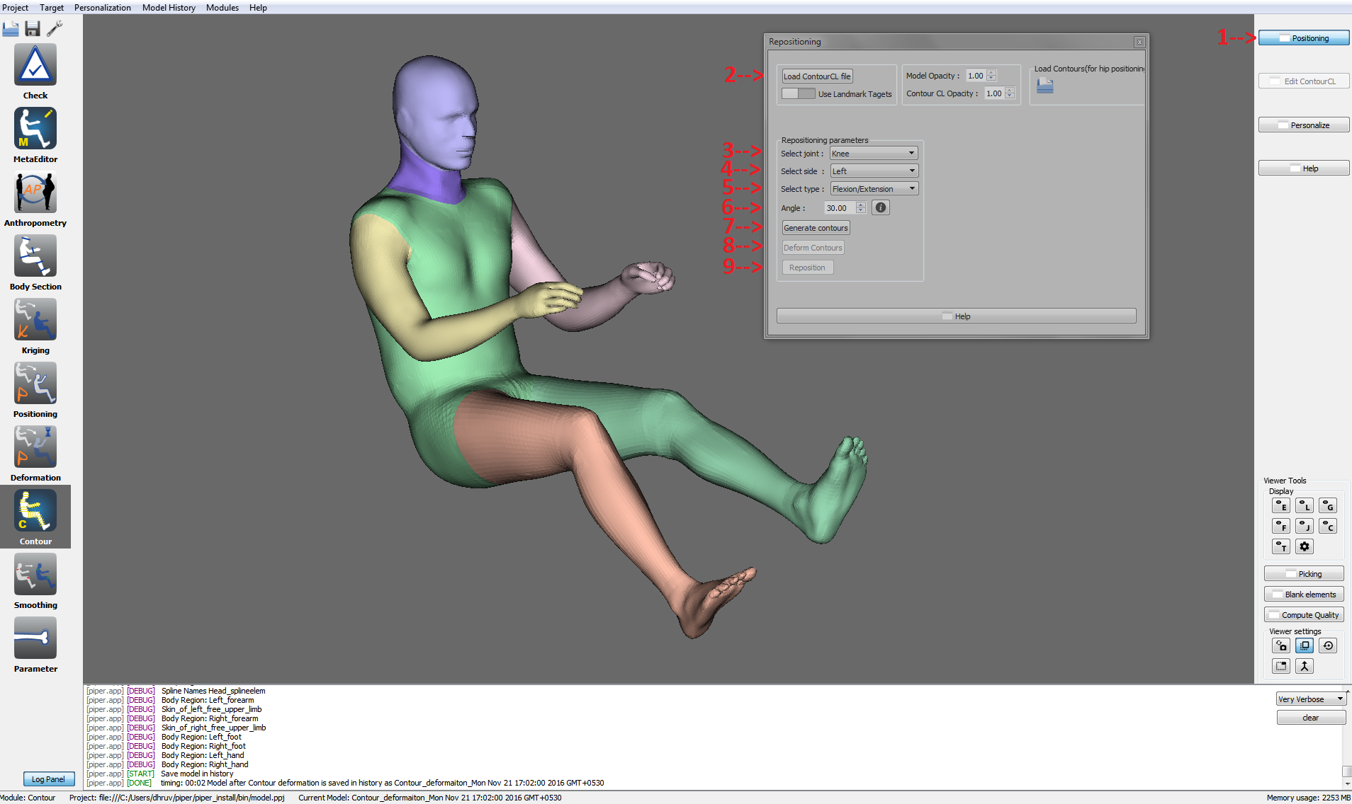
Positioining UI with stepwise description to do repositioning
Steps to re-position the model using the contour deformation module using landmark targets :
- Import the target file using Target Menu
- Go to Contour Deformation Module
- Press Positioning button on the side bar. This will open a new window having controls for re-positioning the HBM
- Press "Load ContourCL file" button to open the contourCL.xml. This step will cause yellow colored control lines to appear with the model display. These control lines provide a guiding structure for the generation of Contours around the HBM. It is also used in the Target Based Repositioning for traversal around the various Body Regions and to find the joint angles.
- Press "Use Landmark Targets" switch to go into re-positioning based on Targets mode.
- The target processing is an iterative process. The body regions are traversed along the contourCL structure. In order to start this iterative process follow the instructions below:
- Press "Process Landmark Targets button". Please note as of now only Landmark Targets are supported.
- The immutable fields Joint,Side, Type and Angle will get populated automatically. Please note, currently only flexion-extension is supported in this Mode.
- Press "Generate Contours" button in order to generate the contours around the HBM.
- Press "Deform Contours" button in order to deform the contours according to the computed Joint,Side,Type and Angle computed in the Step 6-b.
- Press "Reposition" button. This will run the contour based repositioning algo to deform the model, based on information synthesized from Landmark Targets.
- Press "Continue" button to move on to the next target for the remaining body regions, until all the body regions are processed.
- If the computed angle is zero, stop.
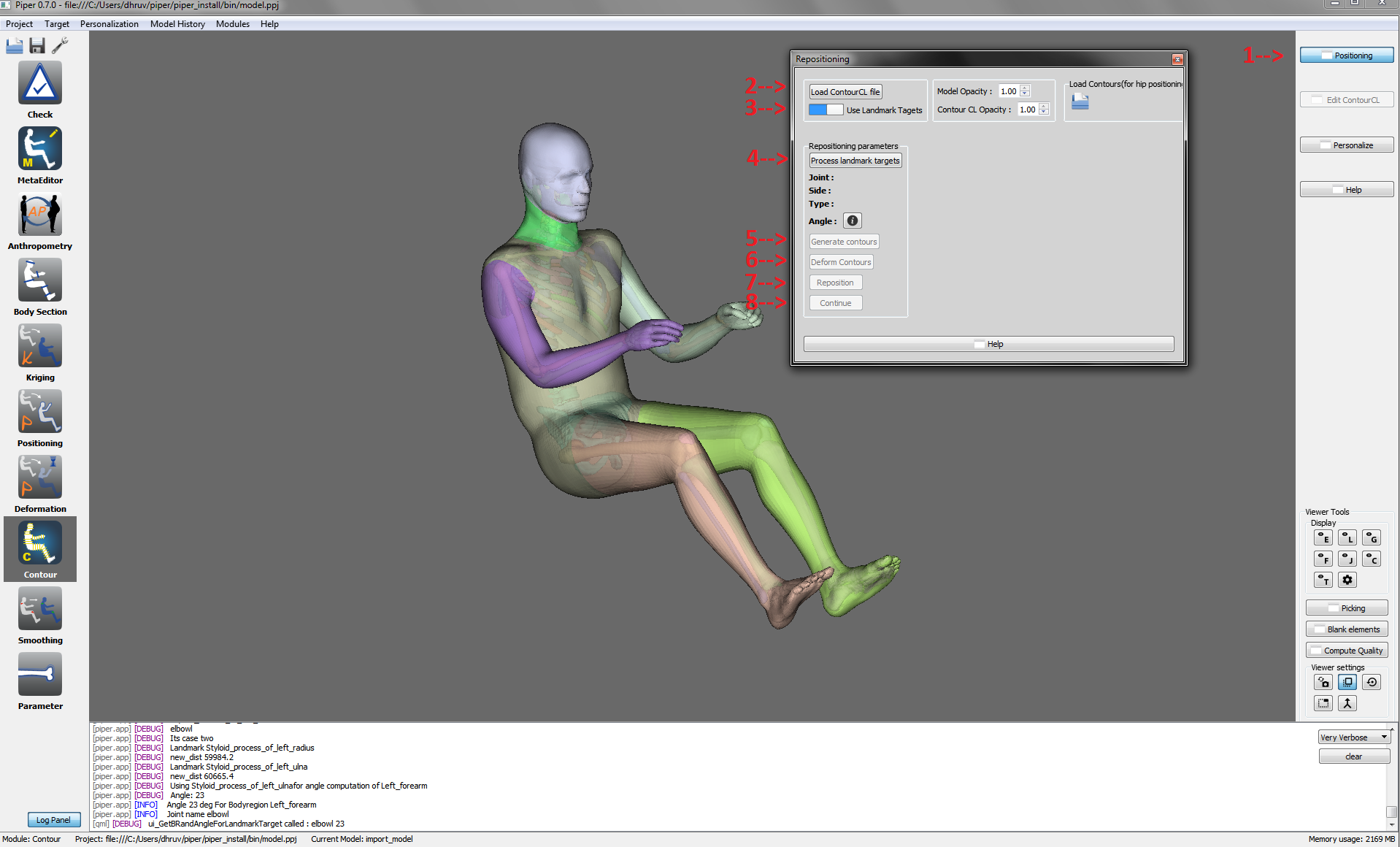
Positioining UI with stepwise description to do repositioning using Landmark Targets
Steps to personalize the model using the contour deformation module :
- 1. Open up PIPER and load the GHBMC model.
- 2. Open Personalization window by clicking on the "Personalization" button on the right panel.
- 3. Click on the "Load personalization contours" button and select the Personalization_Input.txt file to load the personalization contours.
- 4. Click on the "Load body data file" button and select the BodyData.txt file to load the personalization ratios.
- 5. Choose a percentile from the option tab or GEBOD body dimension targets or generate the ANSUR targets.
- 6. Click on the start button to personalize the model.
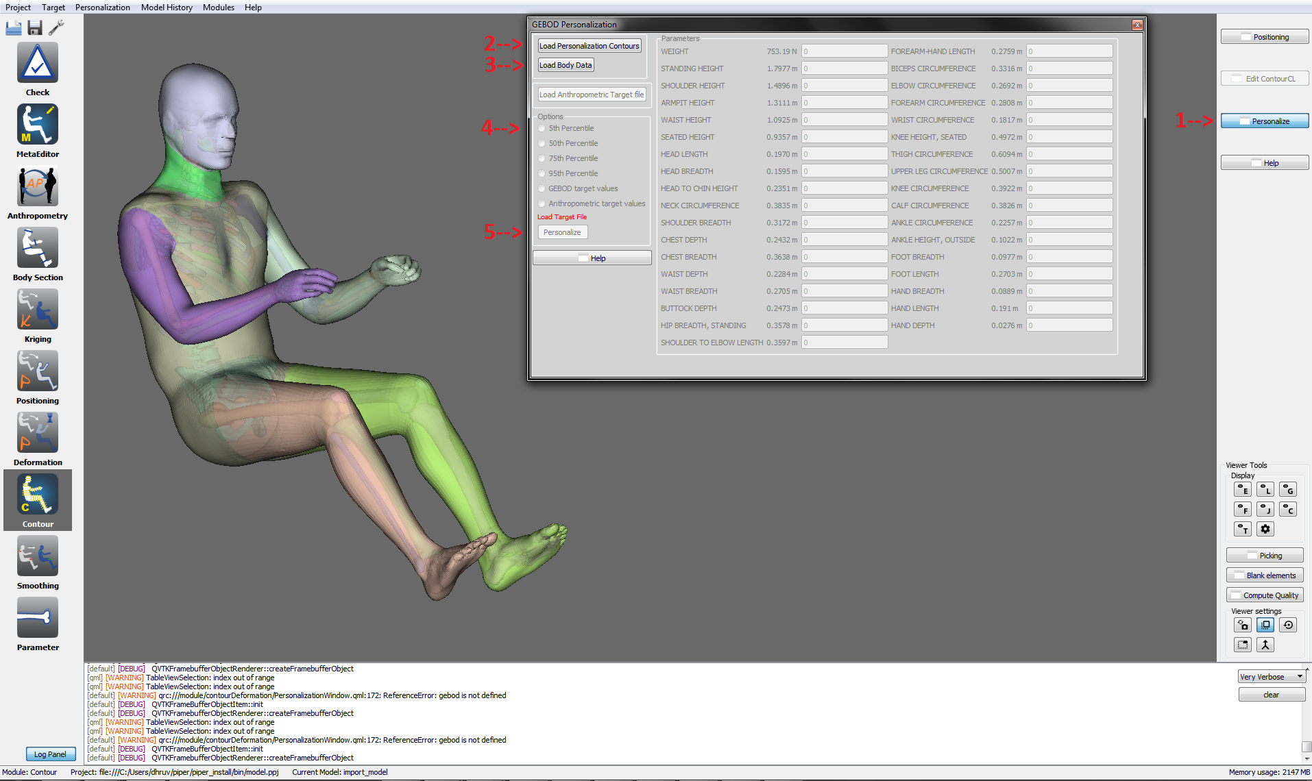
Personalization UI with steps to perform personalization
Steps to reposition the module in case of absence of a required entity (eg. SkinHeadNeck for positioning at cervical region) :
- 1. Open Repositioning window by clicking on the "Positioning" button on the right panel
- 2. Load the contourCL from contourDeformation Module from the path : "{model}\GHBM\metadata\MetaEditorWorkFlowEntityEditor" folder.
- 3. A pop window will propmpt about missing SkinHeadNeck entity.
- 4. Goto MetaEditor Module. Click on Complete contourCL button. A window will pop up showing the missing SkinHeadNeck metadata in the list.
- 5. Click on the missing metadata from the list and click on Create Object button.
- 6. Entity editor will pop up, now proceed as follows :
- 6a) Select the entity picker from the picker options displayed in the entity editor window
- 6b) Open up the Entity display window and selectively display Skin_Of_Head and Skin_Of_Neck entities
- 6c) Click on shift and select the Skin_Of_Head and Skin_Of_Neck entities.
- 6d) Click on add in the entity editor window to create the new entity SkinHeadNeck.
- 7. Now go to contour Deformation Module.
- 8. Open the Positioning window from the right tab.
- 9. Load the contourCL from contourDeformation Module from the path : "{model}\GHBM\metadata\MetaEditorWorkFlowEntityEditor" folder.
- 10. Select the following options in the Repositioning Parameters :
- 10a) Select Neck in the Joint options
- 10b) Select among the following movements : flexion/extension, lateral rotation, lateral flexion/extension
- 10c) Enter the angle by which you want to do the selected movement at the selected joint
- 11. Click on the "Generate contours" button to create the contours and wait for the contours to be generated
- 12. Click on the "Deform Contours" button to deform the contours.
- 13. Click on the "Reposition" button to re-position the model to the new position and wait for the re-positioning to be completed.
Steps to reposition the module in case of absence of a required landmark(eg. footl_distal1 for positioning at ankle joint) :
- 1. Open Repositioning window by clicking on the "Positioning" button on the right panel
- 2. Load the contourCL from contourDeformation Module from the path : "{model}\GHBM\metadata\MetaEditorWorkFlowLandmarkEditor" folder.
- 3. A pop window will propmpt about missing controlpoint landmark footr_distal1.
- 4. Goto MetaEditor Module. Click on Complete contourCL button. A window will pop up showing the missing footr_distal1 metadata in the list.
- 5. Click on the missing metadata from the list and click on Create Object button.
- 6. Landmark editor will pop up, now proceed as follows :
- 6a) Select the single node picker from the picker options displayed in the landmark editor window
- 6b) Open up the Entity display window and selectively display Right_foot_Skeleton entity
- 6c) Click on second distal phalange of the Right_foot_Skeleton entity
- 6d) Click on add in the landmark editor window to create the new landmark footr_distal1.
- 7. Now go to contour Deformation Module.
- 8. Open the Positioning window from the right tab.
- 9. Load the contourCL from contourDeformation Module from the path : "{model}\GHBM\metadata\MetaEditorWorkFlowEntityEditor" folder.
- 10. Select the following options in the Repositioning Parameters :
- 10a) Select Ankle in the Joint options
- 10b) Select among the following movements : flexion/extension, inversion/aversion
- 10c) Select Right in the Side options
- 10d) Enter the angle by which you want to do the selected movement at the selected joint
- 11. Click on the "Generate contours" button to create the contours and wait for the contours to be generated
- 12. Click on the "Deform Contours" button to deform the contours.
- 13. Click on the "Reposition" button to re-position the model to the new position and wait for the re-positioning to be completed.
Contour Personalization
Overview
This module provides various tools for performing personalization on the Human Body Model (HBM) with the help of dynamic contourCL. The main approach of this module is to use contourCL as reference in order to perform personalization routine. The process can be performed in various ways such as Custom Personalization or Target Based Personalization.
Custom Personalization
This tools aims to provide the user to control the dimensions of the HBM in order to perform personalization. Two major tools being :
- 1. Circumference Scaling Tool
- 2. Length Scaling Tool
Custom Personalization: Circumference Tool
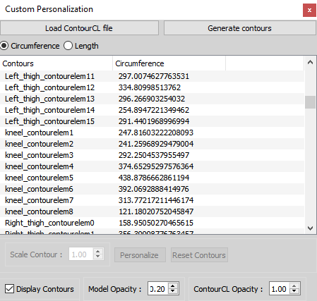
Custom Personalization Window: Circumference Tab
The above snapshot shows the Custom Personalization: Circumference Tool which is used to scale the circumference of the selected contour. The procedure for using this tools is as follows:
-1. Click on "Load ContourCL File" button and select the valid contourCL xml file. -2. Click on "Generate Contours" button in order to Genrate the Contours in the display. -3. Select the contour to be scaled from the provided table. -4. Change the value of "Scale Contour" spinbox and view the results in the display. -5. Click on "Reset Contours" incase of any error and perform the previous step again. -6. Click on "Personalize" button to perform personalization.
Custom Personalization: Length Tool
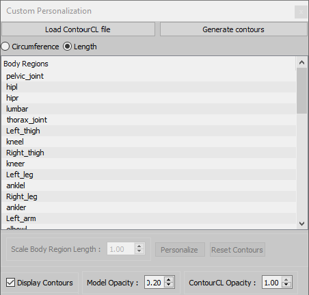
Custom Personalization Window: Length Tab
The above snapshot shows the Custom Personalization: Length Tool which is used to scale the length of the selected contour body region. The procedure for using this tools is as follows:
-1. Click on "Load ContourCL File" button and select the valid contourCL xml file. -2. Click on "Generate Contours" button in order to Genrate the Contours in the display. -3. Select the contour body region to be scaled from the provided table. -4. Change the value of "Scale Body Region Length" spinbox and view the results in the display. -5. Click on "Reset Contours" incase of any error and perform the previous step again. -6. Click on "Personalize" button to perform personalization.
Target Personalization
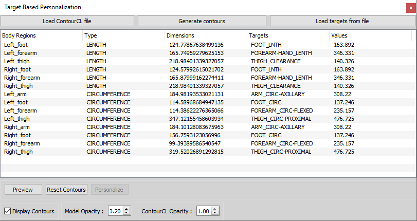
Target Personalization Window
The above snapshot shows the Target Personalization window. this tool provides the user the user to load the Anthrometric Targets generated from the Anthropo Module . The procedure for using this tools is as follows:
-1. Click on "Load ContourCL File" button and select the valid contourCL xml file. -2. Click on "Generate Contours" button in order to Genrate the Contours in the display. -3. Click on "Load Target File" button if the targets have not been loaded yet. The values of the targets will be updated in the table below that button. -4. Click on "Preview" to preview the modified contours. -5. Click on "Reset Contours" incase of any error and perform the previous step again. -6. Click on "Personalize" button to perform personalization.
 1.8.10
