This module implements a physics simulation with a reduced number of degrees of freedom.
Hence the user can interactively position the Human Body Model. The main focus of this module is to define the target bones position of the HBM. The final deformation can be obtained with the Fine-Positioning Module or the Contour Deformation Module. Please refer to Positioning in PIPER: overview for a general introduction.
- Metadata: The skin and skeleton must be defined by Entity, the kinematics of the HBM is constructed from Joint and Contact. More details are given in the Metadata section.
- Input Targets:
- any user defined target (fixed bone, joint, frame to frame, landmark), see also Target
- Output Targets :
- the current user defined targets
- all bones inertia frame position (world frame to inertia frame targets), to work with the Fine-Positioning Module
- all landmarks position
- Output:
- Bibliography: "Stable Constrained Dynamics", Maxime Tournier, Matthieu Nesme, Benjamin Gilles, François Faure, ACM Transactions on Graphics, Proceedings of SIGGRAPH, 2015
- Author
- Thomas Lemaire - INRIA
Metadata
- Entity
- [REQUIRED] Bones and a single Skin or a set of skin entities including Skin_of_head, Skin_of_body_proper, Skin_of_{left,right}_free_upper_limb and Skin_of_{left,right}_free_lower_limb (see the How to...).
- Articular capsules can be defined to make the flesh slide on the bone around a joint. This prevents flesh 3d elements close to the joints to suffer large deformation and quality degradation when the joint moves. Normals at the capsule surface must point outwards the flesh, hence toward the joint center. In conjunction with capsules, the corresponding bony regions included in the capsule must be defined (see below)
- Ligaments must be defined when a capsule is defined, to prevent them from penetrating into the bones.
- For constraints such that bone, and ligament collision or sliding contacts, the normals of the meshes must be properly defined pointing outside.
- Joint, Anatomical Joint and Contact are used to create the kinematics model for the positioning.
- Landmark
- Named Metadata
- custom_affine named metadata define positions where custom affine frames can be added to a deformable entity like skin, capsule or ligament, the naming scheme is custom_affine__Name_of_entity - example: custom_affine__Skin_of_left_arm
- bone_region named metadata define the bone region which is included in a given capsule, the naming scheme is bone_region__Name_of_bone__Name_of_capsule - example: bone_region__Left_femur__Articular_capsule_of_left_knee_joint
Simulation model
The simulation model is built using the geometry defined in the PIPER model, the metadata information is used as follow :
- bones Entity are simulated as rigid bodies, collision constraints are created with consecutive bones (can be disabled)
- the material inside the skin Entity is simulated as a uniform elastic material
- the Joint and Anatomical Joint are added as cinematic constrained
- the Contact defined between bones are also simulated, the distance between the two contact surfaces tries to be maintained
- capsules and ligaments are simulated and collision constraints are created with related bones (can be disabled)
The time needed to build the simulation is typically between less than 1 minute and a few minutes depending on the size of the HBM and the speed of your machine. The simulation is then run in the SOFA Framework.
Parameters
the Pre-Position module can be controlled by parameters, they have reasonable default values and can be defined in the Module parameters dialog. These parameters let degrade the precision of the deformation field, which is not of first interest in this module, in favor of loading time and interactivity.
bone collision
Enable/disable bone collision
articular capsule
Enable/disable articular capsule simulation, which includes : adding affine frames to the capsule to better deform them, the same for ligaments entities, and lastly enable collisions between the capsule surface, the ligaments and the bones involved in that articular joint.
Number of collision vertices
Default number of closest vertices considered in bone, capsule and ligaments collision, if this number is too low bones can oscillate between two collisions. The value can also be changed during the positioning in Simulation control. A value of 0 means all vertices are considered.
Frames per capsule
Set the number of affine frames sampled for each capsule, increase this number if you think the capsules do not have enough degrees of freedom to react to collisions.
custom affine
Enable/disable additionnal affines define in Metadata
voxel size
The input HBM geometry is rasterized in a 3D grid to prepare the simulation model. This parameter controls the size of the voxels of this grid. This value can be decreased if you encounter topological problems in the interactive model (such as close parts being attached one to each other). This value can be increased to make the module loading faster.
voxel coarsening
After the rasterization, various computations can be run on a coarser grid to speed up even ore the module loading. A value of n means 2^n times less voxels, so 1 means no coarsening.
affine density
This parameter controls the density of affine (deformable) degrees of freedom in the flesh. For this Interactive module it can be kept to 0.
tibia/patella constraint
Enable/disable a distance constraint between the patella (center of gravity) and the tibial tuberosity landmark (which then must be defined in the metadata)
User interface
This module UI is composed of a 3D Display and several toolbox windows which are described in the following sections. On the right side a set of buttons let the user select the active mouse interaction, an other set to show/hide the different toolbox windows.
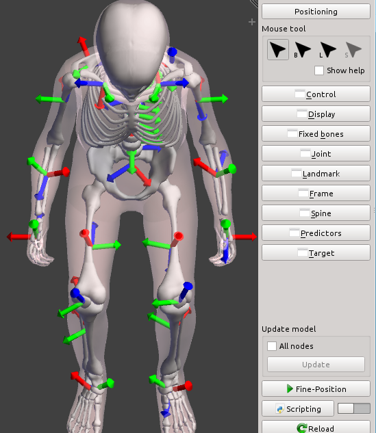
3D view, bone frames are displayed
Interactive positioning
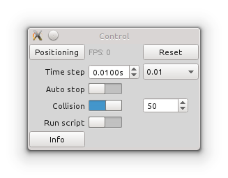
Simulation control
- The positioning process can be started, stopped and reset
- The simulation time step can be adjusted, increase it if you are in a hurry, reduce it when the simulation gets unstable
- The Number of collision vertices can be changed,
- If bone collision are enabled, they can be turn on and off on the fly, to increase simulation frame rate.
- The Run script switch triggers the execution of the lastly run python script after each simulation step (see Scripting).
Positioning controller
A set of controllers allow the user to drive the positioning process, they are described in the following sections.
Fixed bone controller
Select the bones which remain fixed during the simulation in the bones tree, several bones can be selected at once when a body region is selected. Fixed bones can also be selected using the Fixed bone mouse interaction. At least one bone should be fixed, if not your model is likely to "fly around".
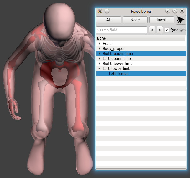
Fixed bones appear in red
Landmark controller
The landmark controller let the user add constraints on any set of landmark coordinates [x,y,z]. Using the mouse interaction, clicking on a yellow landmark select it to add a controller on it. Clicking on a green target makes appear a manipulator according to the controlled DoF of that landmark, the target can then be moved interactively.
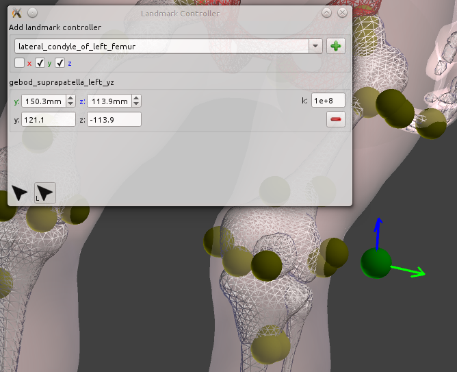
Landmarks are displayed in yellow, targets in green. One target is being set interactively
Joint controller
The cinematic joints defined in the HBM can be controlled (according to their degrees of freedom). Joint frames can be displayed individually for each controller.
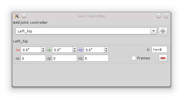
Joint controller
Frame to frame controller
A frame controller is created either:
- between a reference frame and a bone entity, then the relative transformation of that entity in the reference frame is constrained
- or between two frames, in that case the absolute transformation between the 2 frames is constrained.
If  is the target transformation value, the objective is to get
  The available frames are:
- the anatomical frames defined by landmarks (automatically created when landmarks are defined on the)
- the world frames, prefixed by
W_
- the bone inertia frames (automatically created for each bone entity), prefixed by
B_ Also, frames can be displayed individually for each controller. - Warning
- Either all or none rotation parameters can be controlled.
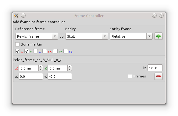
Frame to frame controller
Spine controller
The spine controller enables the user to draw a target Bezier curve for the spine shape. Before creating the controller, a set of vertebrae has to be selected, they are used as Bezier control points (their center of gravity) and the initial curve is computed to go through these points. Using the spine mouse interaction, the curve can be freely modified in 3D. To ease this task you can show/hide disrupting objects in the Display settings.
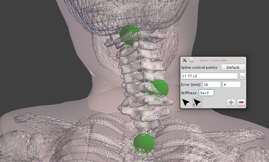
Interactive spine controller, the target Bezier curves and controlled points are drawn in green, also the distance from the vertebra to the curve
Spine predictor
The predictors exploit a priori knowledge (statistical, bibliography study,...) to produce realistic positioning targets. These targets are then used to drive the positioning process.
- Parameters: Posture A, Posture B, Target posture, thoraco-lumbar lateral flexion angle, cervical lateral flexion angle, Align on gravity, gravity vector, Stiffness
- Metadata:
- the ISB landmarks required to compute the vertebrae and the pelvis body coordinate system needs to be defined on the model (see Appendix: List of frames). You can obtain a list of these landmarks by using the
printFrameLandmarks.py standard script, running it with arguments "Spine ISB_BCS" and "Pelvic_skeleton ISB_BCS"
- the Pelvic_skeleton entity is required
- the gravity vector
- Intended use:
- The spine predictor is to be used as a quick and easy physiological pre-positioning tool for the spine segment.
- A possible workflow may be e.g. to use the spine predictor to predict a flexed forward posture and to use any other option (e.g. direct Joint angle definition or frame controller control followed by positioning) to modify the orientation of the head or cervical spine (e.g. to ensure horizontal vision), or to adapt the spinal shape locally (e.g. to a given seat).
Authors: Thomas LEMAIRE - INRIA / Bertrand FRECHEDE - UCBL/IFSTTAR
Overview
The spine predictor computes a likely shape of the spine by interpolating splines between known physiological end-postures. These end-postures represent average postures obtained from published postural in-vivo data in the sagittal plane. As of Piper version 1.0.0 the following end-postures can be chosen by the user: supine, standing erect, standing slouch, seated erect, seated driving, forward-flexed (seated). Lateral bending is controlled separately by the user by defining target angles, but relies on similar interpolations between a reference sagittal posture and published in-vivo Range of Motion (RoM) in lateral bending.
Using the tool
Upon opening the tool the user selects (i) two end-postures (Posture A and Posture B) and (ii) a postural parameter (Target posture cursor in the range [-0.2 1.2]). This parameter represents a percentage of transformation between the two known physiological end-postures. As the end-postures’ global orientation (as defined by their pelvis orientation) is defined relative to the gravity vector, so is the resulting posture by default (align on gravity option on). In practice, this is performed automatically by adding a Frame to frame controller to constrain the pelvis absolute orientation and by rotating the pelvis by its target interpolated value between the two end postures. The vertical is taken as the gravity vector.
Alternatively, the spine resulting from the Target posture value can be aligned to the initial L5 vertebra (align on gravity option off). In this case, the resulting posture is not ‘likely’ in the sense that the spinal shape is not associated with a likely global orientation of the pelvis. Nevertheless, it remains a physiologically acceptable solution among others, thus allowing to define a range of possible spinal postures while keeping the pelvis in its initial orientation.
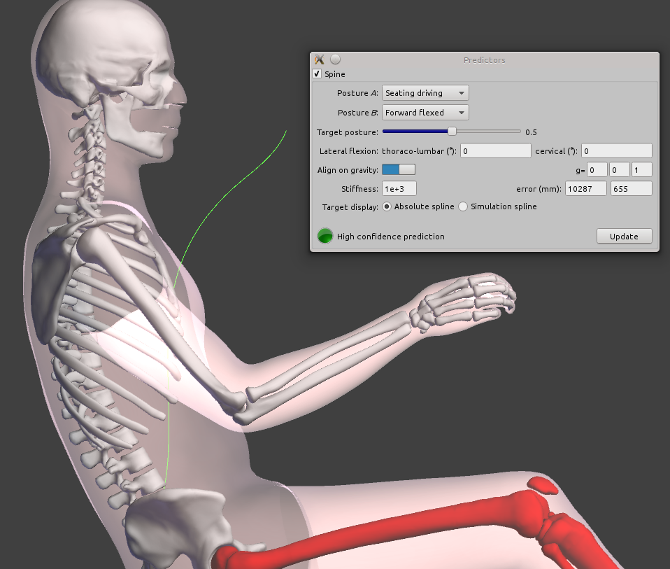
Spine predictor input parameters and output target spline in green
Lateral flexion is controlled independently by entering angles in the thoraco-lumbar and cervical fields. Max. values for these angles are constrained by the physiological lateral (RoM) of the spine. Thoraco-lumbar and cervical curvature prediction are based on published kinematic coordination laws (ratios between the cervical, thoracic and lumbar angles) for the spine in lateral flexion. However results of this prediction (including when used in combination with the above presented interpolation in the sagittal plane) are not considered to be more ‘likely’ than others as they do not rely on reference postural knowledge but only on maximum RoM distribution within the spine.
Additionally, a visual cue (colored circle) and text information is provided to the user as an indicative level of confidence for the prediction, as follows:
- Green circle / ‘high confidence prediction’: this is the case when the transformation is applied in the sagittal plane, within the [0 1] interval for Target posture interpolation.
- Orange circle / ‘medium confidence prediction’: this is the case if:
- The transformation is applied in the sagittal plane within the [-0.1 0] or [1 1.1] intervals for Target posture interpolation,
- OR The transformation is applied outside of the sagittal plane within the following lateral flexion RoM limits: +/- 7.4° for the cervical angle and +/- 27.7° for the TL angle.
- Red circle / ‘low confidence prediction’: this is the case if:
- The transformation is applied in the sagittal plane within the [-0.2 -0.1[ or ]1.1 1.2] intervals for Target posture interpolation,
- OR Any other combination.
If the align on gravity option is off, these levels of confidence concern only the resulting curvature of the spine and the fact that those are within measured RoMs. If it is on, they will also give an indication on the likeliness of the posture (i.e. including spinal curvatures and rotation of the pelvis) based on the source and target end-postures.
Limitations
- The computation of a prediction based on changes between known, absolute physiological postures, requires that any HBM’s spine in input will be transformed to a reference posture in the sagittal plane (as defined by the pelvis bones). This is achieved by performing an initial positioning in this posture prior to computing the transformation from Posture A to Posture B. This step is transparent for the user. However it means that subject-specific curvatures (e.g. aged/scoliotic subject) that would exist in the HBM or Piper model prior to the use of the spine predictor will be lost through the process. Alternate octave scripts are provided as part of the release that allow applying predicted transformations directly to the input spine without going through the initial positioning phase.
- The user’s target/chosen parameters are not saved as part of the history.
Display settings
The display toolbox enables to show/hide (and even draw in wireframe) several items:
- the skin envelop of the model in semi translucent pink if the skin entity has been defined in metadata Entity.
- the bones geometry in white (for bones Entity defined in the PIPER model)
- environment objects
- landmarks, joints frames, anatomical and bone inertia frames, world attached frames
- contact violation as yellow lines
- mesh normals
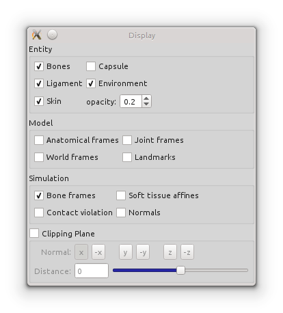
Display settings, bones displayed as wireframe
Output Targets
Several types of targets can be created in the application target list:
- the currently defined user targets, the main interest interest is to replay the same positioning later, or on an other model, or using batch mode
- all HBM Landmark metadata, these targets can then be used in the Contour Deformation Module
- all bones inertia frames absolute position, these targets can be used to deform the model in the Fine-Positioning Module
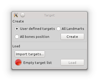
Target creation and loading
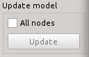
Model nodes update
The computation of model nodes must be activated first, then the PIPER model nodes coordinate can be updated.
HBM nodes update
This module main functionality is not to compute a precise deformation field for the HBM, consider using the Fine-Positioning Module or the Contour Deformation Module for this purpose.
The Deformation button sends you directly to the Fine-Positioning Module executing the following sequence:
- the current user-defined targets are saved to the application target list
- the Fine-Positioning Module is started
- the previously saved targets are loaded in the Deformation module
Scripting
The module supports specific scripting functions to access intermediate states during the positioning process and export any data that could drive an external simulation to achieve the full HBM positioning.
Specific python objects
In addition to the regular PIPER scripting (see Scripting and Batch mode), a script run along with this module can access the currently defined controllers with these 3 python objects: jointController, landmarkController, frameController.
11 if (2 != len(sys.argv)):
12 raise RuntimeError(
"Invalid arguments")
14 controllerName = sys.argv[1]
16 if controllerName
in landmarkController.getControllerNames():
17 controller = landmarkController
18 elif controllerName
in jointController.getControllerNames():
19 controller = jointController
20 elif controllerName
in frameController.getControllerNames():
21 controller = frameController
22 if not controller
is None:
23 piper.app.logInfo(
"Controller: {0} - target: {1} - mask: {2} - position: {3}".format(controllerName, controller.getTarget(controllerName), controller.getMask(controllerName), controller.getCurrentPosition(controllerName)))
25 piper.app.logInfo(
"Controller {0} does not exist".format(controllerName))
Also the current position of the HBM can be saved in the Model history using the simulationController
12 model = piper.app.Context.instance().project().model()
16 piper.app.logWarning(
"Model is empty")
17 elif not simulationController.isAllNodesActivated():
18 piper.app.logWarning(
"\"all nodes\" update is not activated")
19 elif (2 != len(sys.argv)):
20 raise RuntimeError(
"Invalid arguments")
22 historyPrefix = sys.argv[1]
23 global historyPrefixCounter
24 if not "historyPrefixCounter" in globals():
26 historyPrefixCounter = dict()
27 if not historyPrefix
in historyPrefixCounter:
28 historyPrefixCounter[historyPrefix] = 0
29 historyName =
"{0}_{1}".format(historyPrefix, historyPrefixCounter[historyPrefix])
30 piper.app.Context.instance().addNewHistory(historyName)
31 historyPrefixCounter[historyPrefix]+=1
32 simulationController.updateModelNodes()
33 piper.app.logInfo(
"Current HBM nodes position saved in {0}".format(historyName))
How to...
How to fix one bone with respect to an other one ?
- If there is a robotic joint defined between the two bones, you can add a joint controller which constraints the relative bones position to stay the same
- In the general case you can add a frame controller between both bones (either 3 rotations, or 3 translations or both) to achieve it
How to reach a complex position ?
You can concentrate on positioning a sub part of the HBM, then fix the corresponding bones and continue the positioning task on an other sub part of the HBM.
The skin of the arm looks attached to the body, how to fix it ?
Depending of the initial position of your HBM, the rasterization process used to set up the simulation might attach close parts of the skin. To get rid of this kind of problems you can split your skin entity in several entities, at least close skin parts should be put in separate entities.
The simulation is unstable even with no target
If you have bone collision enabled try to disable it in the Module parameters, if this fixes the problem it is likely that you have wrongly defined normals for some bone meshes. You can check the normals using the Display settings in this module, or the Generic viewer in the Check Module, and fix them in your favorite preprocessor software.
 1.8.10
