|
PIPER
1.0.1
|
|
PIPER
1.0.1
|
This page provides basic documentation on the Graphical User Interface (GUI) of the PIPER application.
The main window is composed of:
Ctrl + Shift + specific letterThe toolbox windows let the user organize his display, even on multi monitors setups, according to its current task. Moreover the size and position of the toolbox windows are persistent through executions of the application.
.ppj file..pmr file metadata with selection of metadata types to import 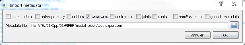
.pmr file with selection of metadata types to export. All current metadata of selected types are deleted and replaced by imported ones. 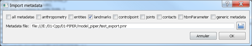
.ptt file..ptt file.All actions that modify the loaded model create a "history node" in the history menu. You can use this menu to undo those action. The history is linear, i.e. it is not possible to do multiple "branches": if you undo an action, you can redo it, but if you undo, then do some other action, the previously undone action will be lost forever. The current state is highlighted in the menu by bold font. The "state" is effectively the coordinates of the nodes of the model.
Available modules integrated in the PIPER application can be selected in the module selection panel, see PIPER Modules Overview page for documentation on each module. The application starts with the Check Module loaded.
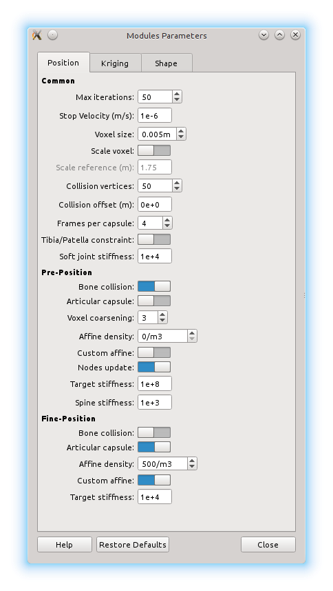
Some modules have parameters which can be set in the Module Parameters dialog accessible in the Project menu and a tool icon. The description of these parameters can be display with the Help button. The modules parameters are saved in the project .ppj file.
The interactive navigation is performed using the mouse :
The left click is kept for interactive manipulation in the 3D view.
The application integrates two distinct viewer: The Physics simulation viewer available in physics based modules and the Generic viewer in other modules.
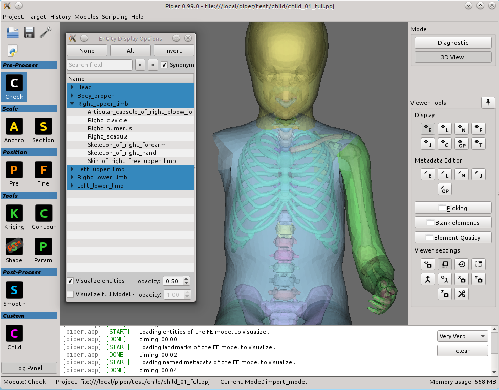
The generic 3D viewer is a tool available in all modules where visual exploration of the data is relevant or helpful. Figure Generic 3D viewer: Tools shows an interface of a module using the generic viewer. The marked GUI controls operate tools available in the viewer: Display Settings - under number 1 in the Figure - provide a few additional options to control behaviour of camera and some rendering options; Display Options - under number 2 - are used to choose which parts of the loaded project should be displayed and which should be hidden; Picking - under number 3 - provide useful tools for selecting any part of the model seen on the screen using mouse; and Blanking - also under 3 - is a simple, yet effective tool to further ease exploration of the model by removing selected elements.
Each module that uses the generic 3D viewer is using the same "instance" of it. This means that whatever settings you change, data you load, the way you move the camera etc. will remain the same when you switch to another module. An exception for that are data that are module specific - for example, kriging control points you load in the Kriging Module will be removed from the viewer once you leave the module.
The display is capable of displaying all the geometry and metadata in your project. However, some features, such as e.g. highlighting of selected points, displaying normals, landmarks and others, require a graphic card with OpenGL 3.2 capabilities. OpenGL 3.2 is a standard from the year 2009, so you should not run into problems if your computer is not older than that. If it is, you will be warned in the application log. Some of the features will switch to using a "legacy code", so you should still be able to use them, but the performance will be significantly slower and might have some bugs, as the "legacy code" is not tested very thoroughly.
If you encounter some problems or glitches related to the 3D viewer, please first make sure that your graphic card drivers are up to date before reporting the issue.
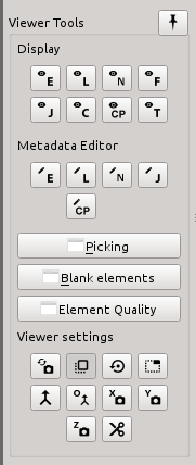
The group of "display settings" buttons currently consists of five buttons in two rows. The first row serves to manipulate the camera by which the scene (your model) is observed, the second row contains tools for displaying geometrical properties of the model.
Camera settings (functionality of each button, from left to right):
Geometrical properties (functionality of each button, from left to right):
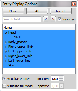
In this group of buttons, there is one button for each type of metadata (left to right, top to bottom): entities, landmarks, generic metadata, frames, joints, contours and targets. Upon clicking it, you will open a window similar to the one in Figure Display options (that one is for the "entity" metadata type). By clicking on each object in the list, you will hide or show it - by default, everything is shown. There are also buttons for showing all, hiding all and inverting the selection.
The last button in the group contains visual settings, allowing you to change the colours, opacity and other visual properties of the metadata.
The "entity" window also contains two additional checkboxes: "visualize entities" and "visualize full model". This allows you to choose the mode in which the model is displayed - either as a set of multiple objects, one for each entity as they are defined by your metadata; or as a single mesh consisting of all the elements in the model. Since they obviously exist in the same place, you will usually want to have displayed only one of them, although you have the option to see both, which might be useful in conjuction with Blanking or the opacity settings (right next to the entities).
Upon clicking the "Picking" button in the right-hand panel, a pop-up window with picking tools will open - see the Figure below. In Piper, "picking" is the word we use for "selecting using the display". Whenever you need to select something, you will find all the available tools in this window. All selection is persistent across all modules that use the generic 3D viewer - what you select in one module, you can process in another one. Selected objects will be highlighted by bright green colour.
Hint: Note that in some cases, especially in the case of picking elements, the objects need to be coloured in another way - for example based on the element quality. This will disable the selection highlighting, but will not de-select the elements! They will still be selected - to turn the selection highlighting back on, simply click on some element picker (see below) and the "highlighting by selection mode" will be turned on again (while, naturally, "highlighting by quality" will be turned off).
The first part of the window is a grid of buttons called "Pickers". Each of the buttons initializes some type of picking on a specified "target". Currently, there are three different types and five different targets, though not all combinations are available. Before explaining each of them, a few general notes:
Picking types:
Picking targets:
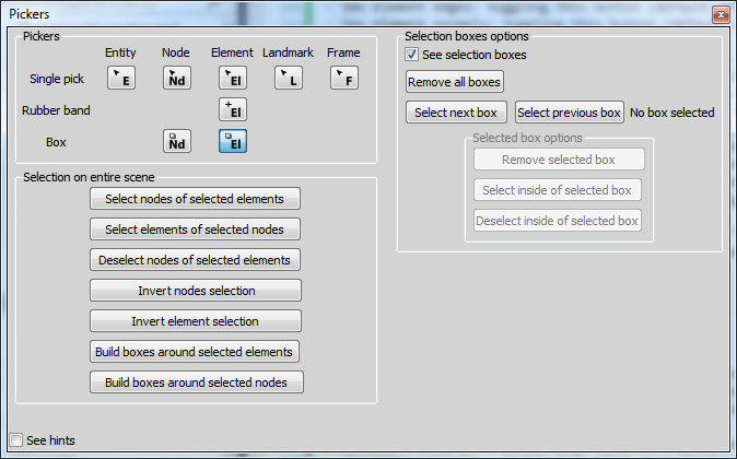
Second part of the Picking window - "Selection on entire scene" - contains several buttons for performing global selection tasks, most of them rather self-explanatory. The tasks are performed on each object that is in the scene and is visible. The last two buttons in the that group - "Build boxes..." - server to create a selection box around selected elements and nodes. Note that clicking these buttons will not perform any actual selection, only creates the boxes - those can than be used for selection using the "Selection boxes options" (see below) or other tasks, e.g. in the Transformation smoothing. A simple algorithm for point clustering is used for building the boxes - the points/elements are clustered and box is built around each cluster. While the algorithm will work well for some basic cases of well defined clusters, in many cases a manually constructed box will have a better fit.
The last part is "Selection boxes option". You have to select some box picker to make this part of the window enabled. It groups together several control elements for using selection boxes (from top to bottom):
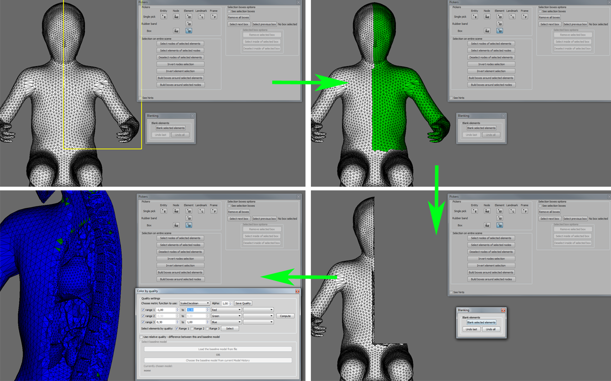
Element blanking is a simple tool that allows you to explore the inside of your FE model. Normally, you can only see the outer shell of your model and even with transparency, you cannot inspect the shape of internal elements. With blanking you can "cut off" part of the model to look inside. Upon clicking the "Blank elements" button, a simple window with three buttons will open: blank selected elements, undo last and undo all.
The first button will remove all elements that are currently selects among all visible objects. See Picking for description of the picking tools you can use to make the selection (box selection is probably the most useful for the purpose of blanking). Note that the blanking is done only on the visual representation of the model - it does not actually change your FE model, it is not an editing tool, simply an exploration tool.
The other two buttons serve for undoing. Undo last will undo the last action, while undo all will return to the original state. Although there is no re-do action, the elements selected before the blanking remain selected after the undo, so you can toggle back and forth between two blanked states (but going back more than one step will lose the latest selection entirely).
The following figure shows an exemplar workflow for model exploration using blanking - selects a part of the mesh by box, blanks the selection and then uses the VTK toolkit Quality metrics to inspect quality of elements inside the model:
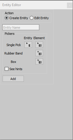
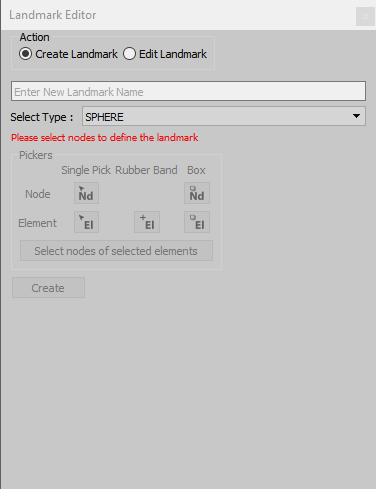
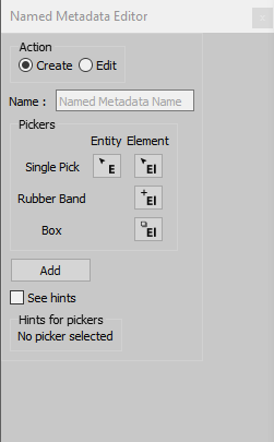
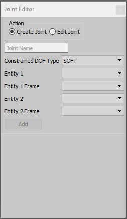
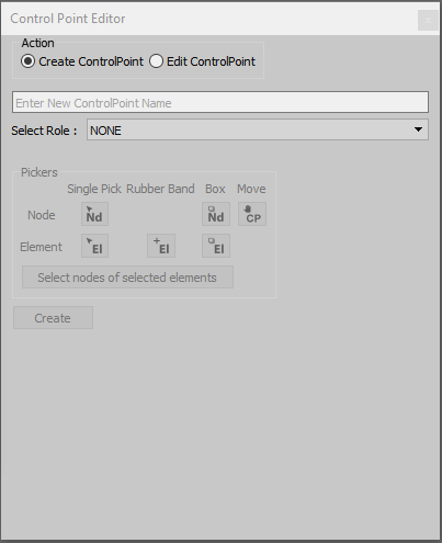
In this group of buttons, there is one button for each type of metadata for editing the respective type of metadata (left to right, top to bottom): Entity Editor, Landmark Editor, Named Metadata Editor, Joint Editor, Control Point Editor.
This viewer is utilized in the Pre-Positioning Module and Fine-Positioning Module modules. The model displayed in this viewer is derived from the loaded FE model specifically for the purpose of physics based positioning. This means that the tools available in the Generic viewer are not available here, because the displayed model is technically not the original one.
Additional navigation tools in the Physics simulation viewer are:
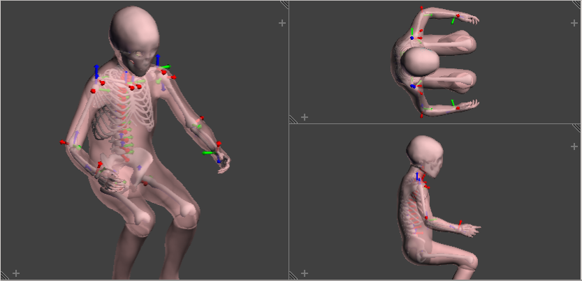
MultiView display is available by drag+dropping the very Top-Right corner of the 3D context towards the left hand side or towards the bottom. Alternatively, the bottom-left corner offers the same functionality in opposite directions.
In order to remove the Multiple views created, one has to operate backward, namely drag+dropping the very Top-Right corner of the multiple (sub) 3D context towards another sub 3D context located on its right side or on its upper side. Alternatively, the bottom left corner offers the same functionality in opposite directions.
The creation order should be reversely followed, for instance in the following image, one of the two vertically stacked 3D display context should be merged (removed) with the other one before trying to remove the remaining left or right 3D display context.
 1.8.10
